2025 FRC Robot: Manta
As electronics lead, I led the team into our first two electrical-fault-free comps in recent memory, and spearheaded the team's first season using computer vision.
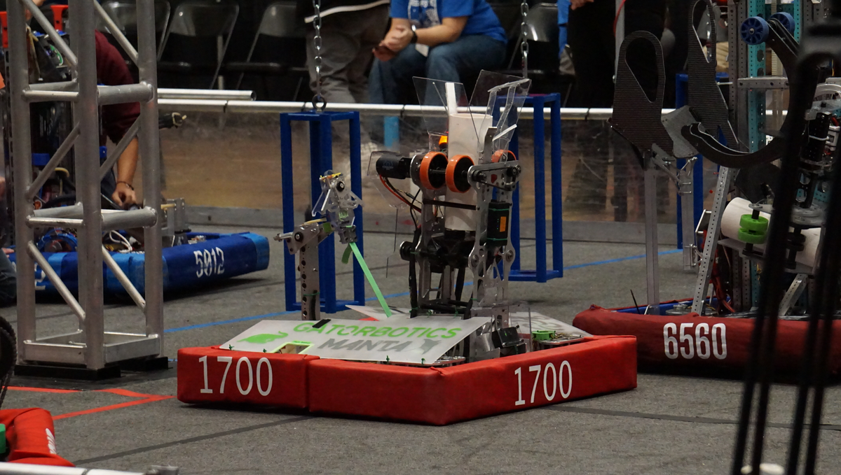
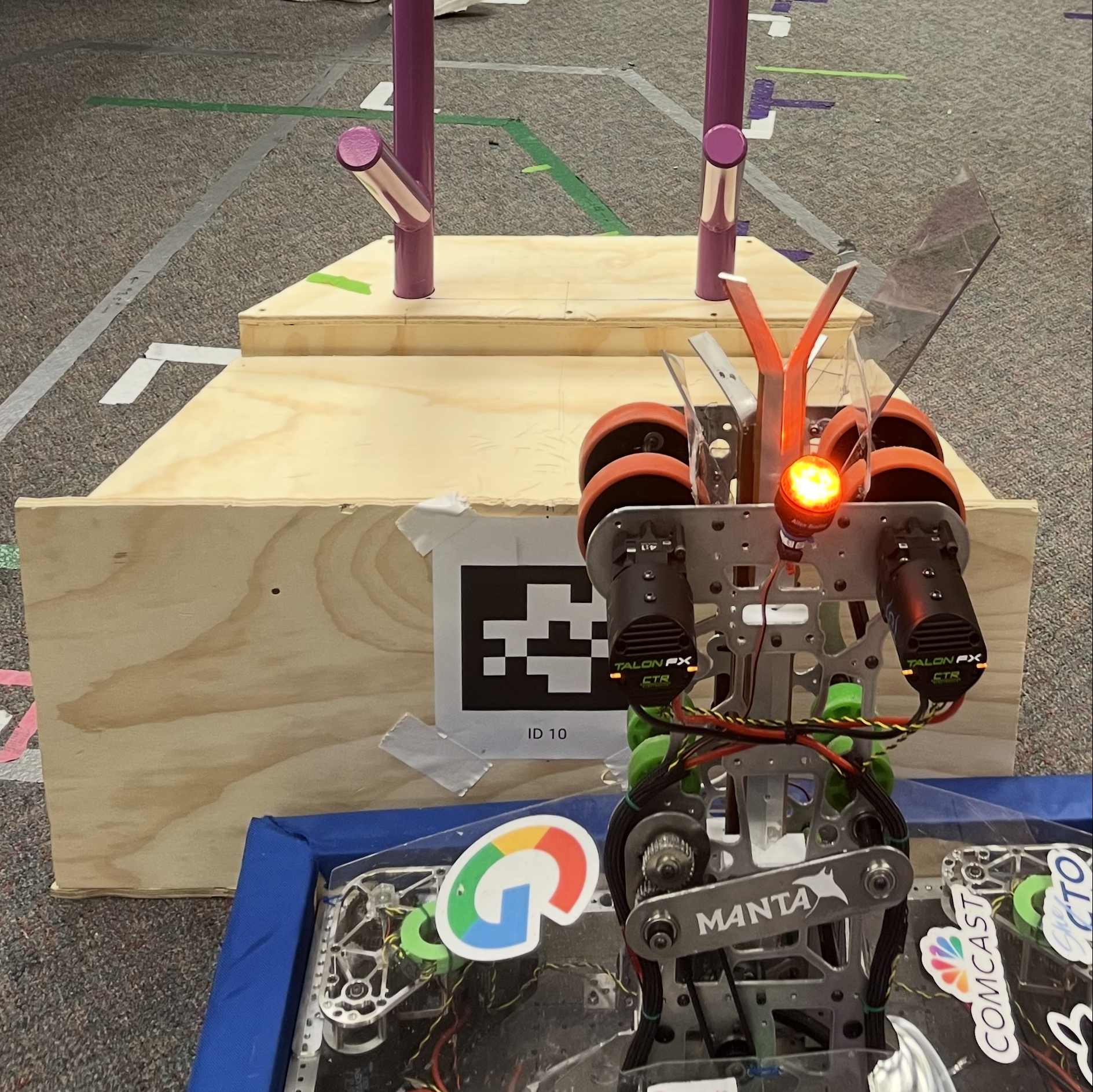
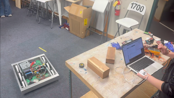
For Reefscape (the 2025 FRC game), our team opted to build a coral shooting robot for shorter cycle times. Computer vision was essential for lining up with the reef (scoring element), as a human driver would not be able to line up consistently enough for the level of precision the shooter required. My biggest personal contributions were to the electrical and vision systems of the robot. We were able to use computer vision to line up with field pieces for the first time this season, and had the first two consecutive electrical-fault-free competitions in my time on the team. You can see our robot reveal video here: https://www.youtube.com/watch?v=rGI5sdL7muw, and a shorter clip of a shot below:

Electronics
For as long as I have been on Gatorbotics we have struggled with electrical failures in matches, often leading to our robots being dead on the field.
As the electronics lead I researched, designed, and implemented solutions to greatly increase the robustness of our electrical systems. The changes I made were:
- Better wire connections
Having tested wago connectors and wire nuts during preseason, I decided to switch us back to molex connectors, which the team had previously abandoned due to the tendency to crimp incorrectly.
The solution to this problem was pre-crimping, which allowed members of the electronics team to move components and wires around easily. Connections were tested before they went on the robot. In our three competitions, we had zero molex connection failures.
- Implementing Ferrules
In our first competition I saw issues in the ways we plugged wires into our components, especially with our small wires. To remedy this we began crimping ferrules onto the ends of these wires to give the terminals more surface area to grab onto.
- Wire routing
To keep everything secure I cable wrapped the majority of our wires and zip-tied these bundles to hold them in place. Signal wires were contained using the cable disks I designed during preseason.
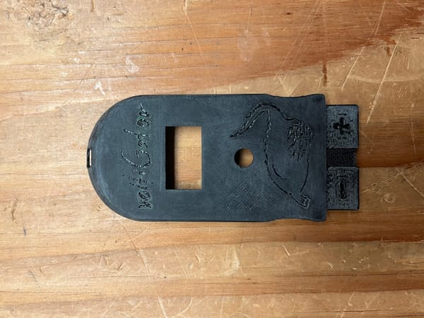
4. 3D Printed Mounts
To ensure components didn't shift in matches I designed a series of 3D printed mounts for components that were more difficult to bolt directly to the robot.
The result of these changes was two consecutive competitions with zero electrical failures, the first two I have seen as a member of Gatorbotics.
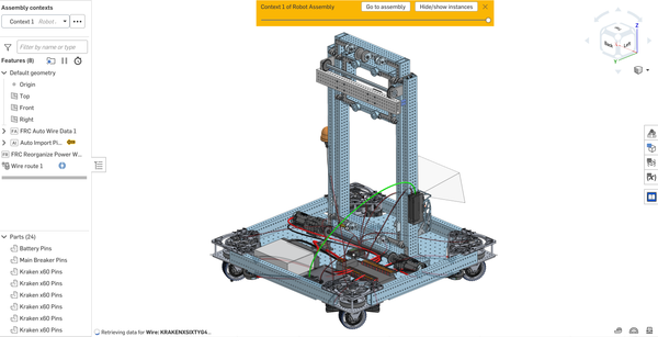
You can see images of the final robot wiring below:
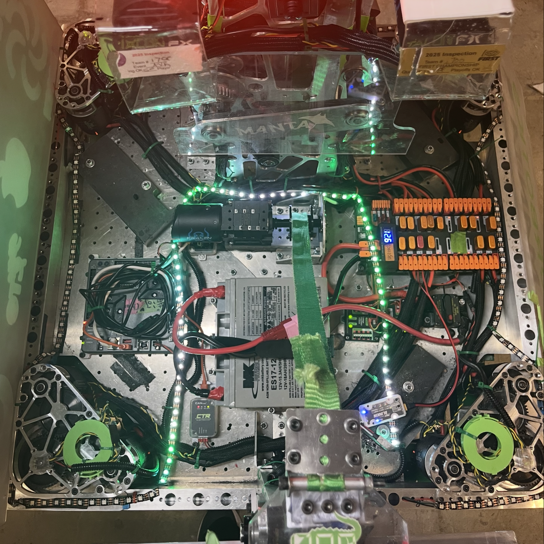
In addition to improving the robustness of the overall system, I also implemented a new component this year: the CTRE CANivore. This small device enables the CAN FD bus protocol, a more efficient version of the CAN bus signal protocol supported by the standard FRC robot. This upgrade lowered our bus utilization, making room for an increased update frequency on our vital drivetrain encoders.
Computer Vision
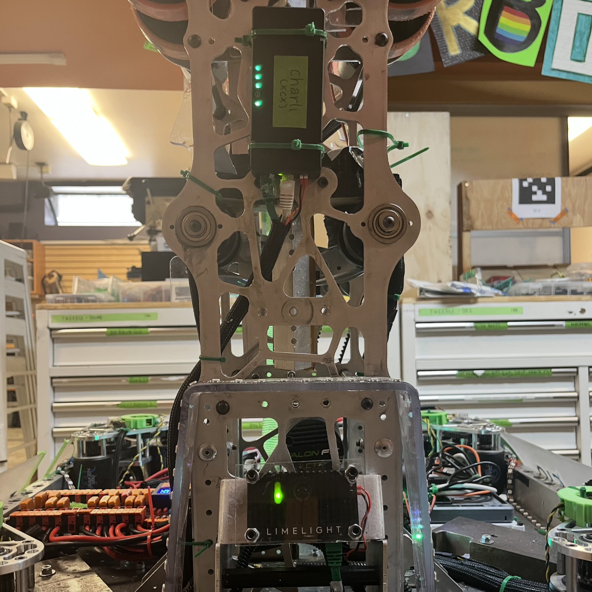
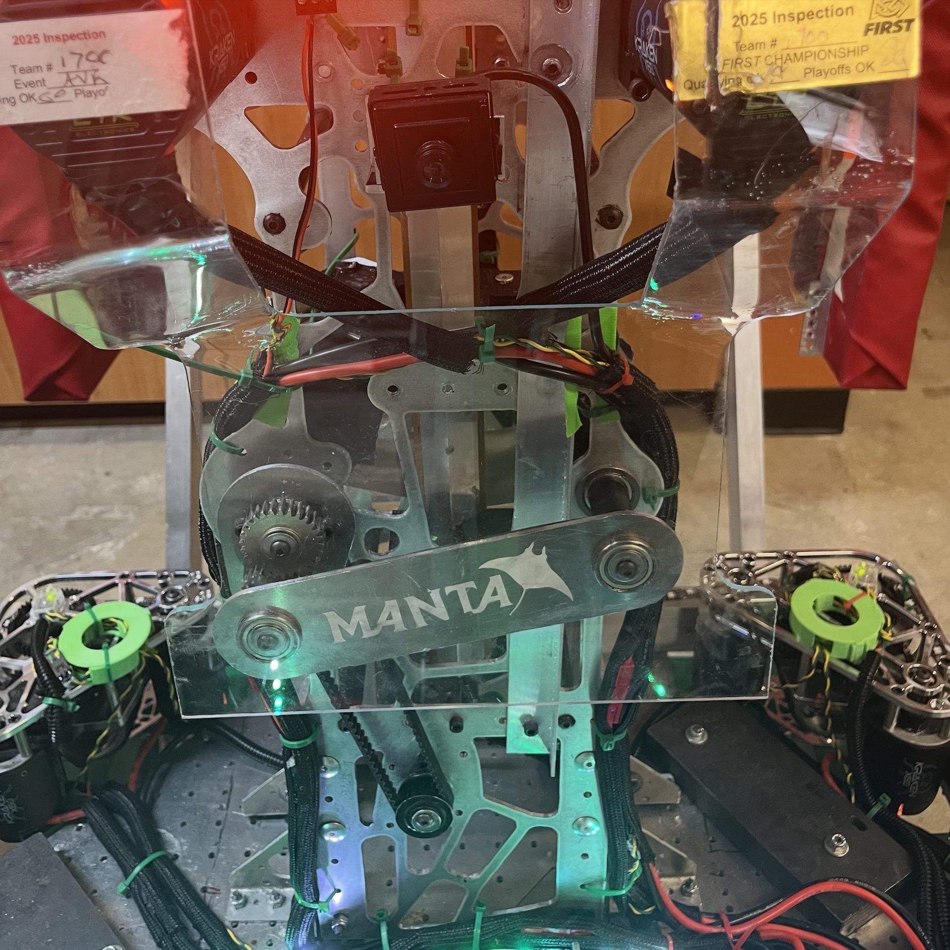
This was the team's first year using computer vision on our robot.
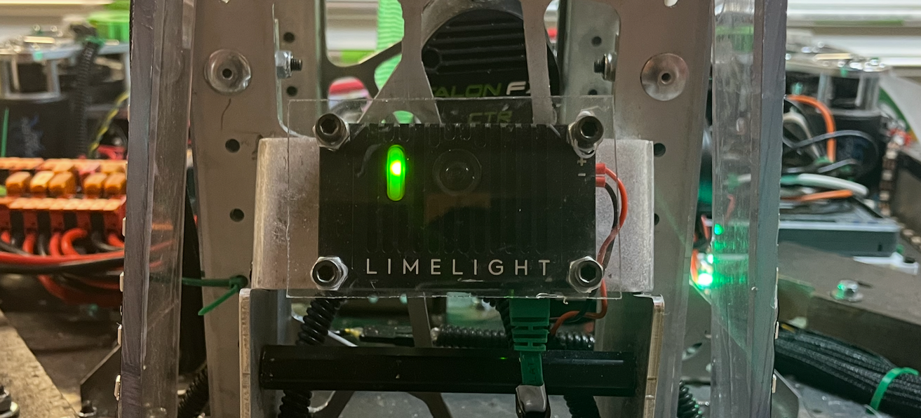
The camera we use (Limelight 4) gives us the position of the AprilTags (consistently placed QR codes) relative to the camera. Our drivetrain methods take in an input of a desired position in field relative coordinates, so most of my work involved transforming the camera relative positions of the AprilTags into field relative coordinates that we could drive to.
I initially tried to do this using trigonometry, but those diagrams got ugly very quickly and one of our mentors pointed out that vector transforms would be much simpler. I wrote new methods in our limelight subsystem to convert the AprilTag's position to field relative coordinates, and extended it to calculate the point that the robot's center needed to be in to line up with the AprilTag.
public Pose2d aprilTagPoseInFieldSpace(Pose2d robotPoseInFieldSpace, Pose2d lineUpOffset) {
    // distance to the camera from the tag (in camera's coordinate space)
    double[] aprilTagArrayInCameraSpace = limelightTable.getEntry("targetpose_cameraspace").getDoubleArray(new double[6]);

    if(aprilTagArrayInCameraSpace == null){ // idk if this is really necessary but better safe than sorry?
        return null;
    }

    Pose3d aprilTagPoseInCameraSpace = arrayToPose3d(aprilTagArrayInCameraSpace);
    Pose2d aprilTagPoseInRobotSpace = convertCameraSpaceToRobotSpace(aprilTagPoseInCameraSpace);
    Pose2d aprilTagPoseFieldSpace = convertToFieldSpace(aprilTagPoseInRobotSpace, robotPoseInFieldSpace);
    Pose2d aprilTagPoseOffsetFrontCenter = offsetToLineUpPoint(aprilTagPoseFieldSpace, lineUpOffset);
    return aprilTagPoseOffsetFrontCenter;
}

public Pose2d convertCameraSpaceToRobotSpace(Pose3d poseInCameraSpace){
  // Create the 3D pose of camera relative to robot center (it's just the limelightOffsets but it makes more sense if you name it cameraPose)
  Pose3d cameraPoseFromRobotCenter = limelightOffsets;

  // Transform the camera pose by the input pose
  Transform3d transform = new Transform3d(poseInCameraSpace.getTranslation(), poseInCameraSpace.getRotation());
  Pose3d robotSpacePose3d = cameraPoseFromRobotCenter.transformBy(transform);

  // Project to 2D by taking x/y components and yaw
  Pose2d robotSpacePose = new Pose2d(
      robotSpacePose3d.getX(),
      robotSpacePose3d.getY(),
      new Rotation2d(robotSpacePose3d.getRotation().getZ()));
  return robotSpacePose;
}

Pose2d convertToFieldSpace(Pose2d targetPoseInRobotSpace, Pose2d robotPoseInFieldSpace) {
  //defines a transform
  Transform2d transform = new Transform2d(targetPoseInRobotSpace.getTranslation(), targetPoseInRobotSpace.getRotation());
  //applies the transform to the pose (transforms the robot's pose by the target pose)
  Pose2d fieldPose = robotPoseInFieldSpace.transformBy(transform);
  return fieldPose;
}

//offsets a pose so that a robot relative lineUpPoint will be aligned with the AprilTag instead of the robot center
Pose2d offsetToLineUpPoint (Pose2d targetPoseInFieldSpace, Pose2d lineUpPointRobotSpace){
  //we flip x and y because logically we want to move the center of the robot back by the offset in order to align the point with the apriltag (because we can only drive to a pose by giving it a target pose for the center)
  Transform2d transform = new Transform2d(
    new Translation2d(-lineUpPointRobotSpace.getX(),
    -lineUpPointRobotSpace.getY()),
    lineUpPointRobotSpace.getRotation());
  Pose2d result = targetPoseInFieldSpace.transformBy(transform);
  return result;
}
I then used these methods in a command that would take in a limelight pipeline (essentially a designation of which AprilTag we wanted to align with) and a lineup offset, and send the drivetrain a calculated desired position.
The benefit of using this approach rather than trying to align with pre-programmed coordinates was that this command could be used for any AprilTag on the field, and tailored to fit any lineup offset. This versatility allowed us to use the same command to line up centered with the AprilTag for one scoring command, and line up offset to the left or right for another. Our robot was able to make shots onto the reef this season because for the first time in the team's history we were able to use computer vision to line up with the AprilTags. You can see an example of this lineup and shot below:
And here's a better angle of where the AprilTag actually is: