Encoder
I designed my own encoder using a color sensor, and used it to enable a motor to react to external input!
For my Engineering II final project I chose to design a functional optical encoder, which I used to program a motor to resist external changes.
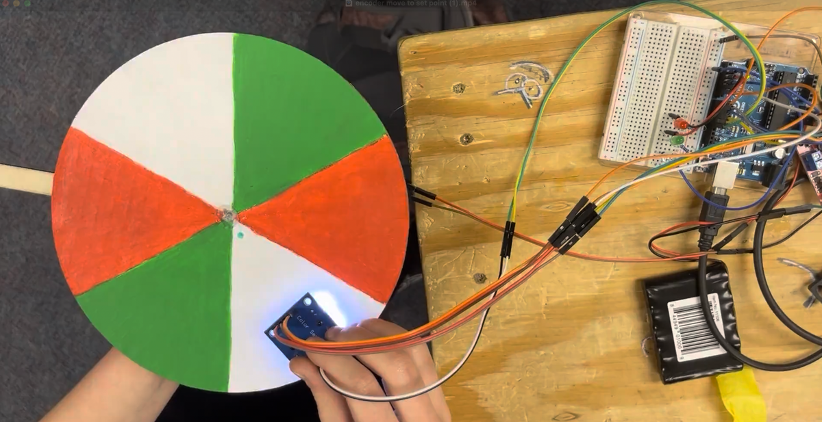
My initial plan was to make an encoder and use it to build a PID controlled arm. I wanted to arm to hold a set point even when a human moved it up and down, so the encoder needed to track changes in direction as well as distance traveled. To be able to detect that direction change, I decided to use a cardboard disk with three colors, and a color sensor to read the color changes. The three colors created a pattern that corresponded to the direction of rotation.
This is what the code logic looks like for calculating the motor ticks:
void updateTicks(){
  int ccolor = color();

  if(ccolor == green && previousColor == red){
    ticks --;
  }else if(ccolor == red && previousColor == white){
    ticks --;
  }else if(ccolor == white && previousColor == green){
    ticks --;
  }else if(ccolor==white && previousColor == red){
    ticks ++;
  }else if(ccolor == red && previousColor == green){
    ticks ++;
  }else if(ccolor == green && previousColor == white){
    ticks ++;
  }
}
I used a cheap color sensor off of amazon, an Arduino Uno, a small hobby DC motor, and some LEDs to visualize what colors the sensor was reading.
I initially had some errors with the update frequency, but I realize this was because I was using serial prints, and my serial update frequency was too low. Once I increased that value I was able to track the rotation of the motor.
The next step was getting the motor to turn to a set point. That worked, but only with a dead band of 1 tick—and with only 6 ticks per revolution that was a substantial amount of error. To get the accuracy within 1 tick I needed to minimize the overshoot, but I was already running the motor at the slowest speed it would actually turn. I could have slowed it down with gear ratios, but I wanted to save the gearing for the arm portion to maximize the revolutions of my encoder per revolution of the arm. Instead, I wrote a method to alternate the voltage to the motor, jittering it to get it to a rough speed percentage:
//an alternative to TurnMotor, this takes in a rough percentage and if it would result in a speed lower than the stall speed (120) it twitches the motor at a proportional rate
void TurnMotorPercent(double percent){
  int speed = 255*percent;
  if(speed > 120 || speed < -120){
    TurnMotor(speed);
    return;
  }

  int sign = 1;

  if(percent<0){
    sign = -1;
    percent = -percent;
  }

  TurnMotor(0);
  delay(50 + 25*(1-percent));
  TurnMotor((percent+0.47)*sign*255);
  delay(30+25*percent);

}
With this method, I was able to get the motor to rotate to a set point using proportional control (I didn't use the derivative or integral components because the motion was inherently jittery, so smoothing it out with a full PID would have little noticeable affect):
I ran out of time to create a full geared arm, but as a proof of concept I attached a small wooden arm directly to the motor shaft and was able to use it to turn the motor and see its response: