Onshape Features: FRC Wiring
My FRC team has struggled to include electronics in our robot design in the past, so I extended Onshape's wiring features to be more user friendly for FRC CADers.
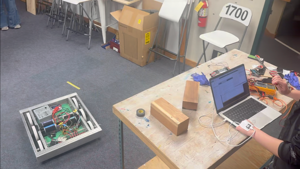
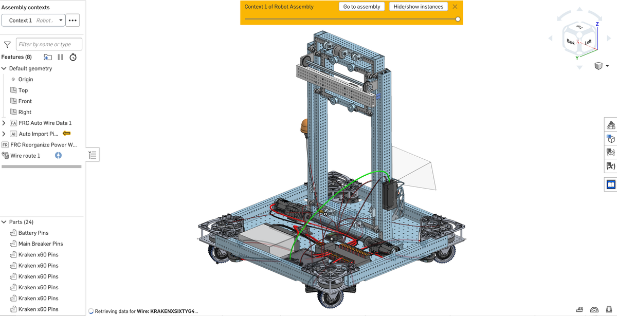
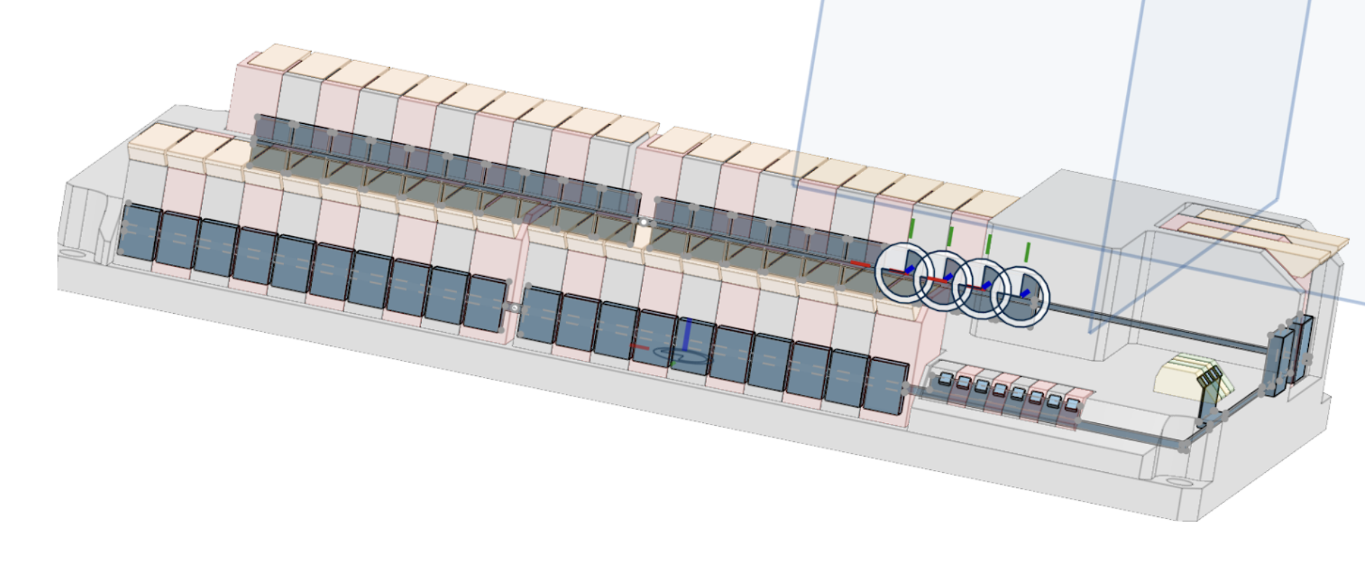
You can see a sample robot (not CADed by me) wired with my features, in addition to my features and custom parts here!
Note: I used Cursor AI for this project, primarily to translate my logic and concepts into a coding environment I was unfamiliar with going in. I still had to troubleshoot the AI-written code, and by the end of the project I was writing most of the code by hand as I got more comfortable with the language.
The existing features required the user to assign each pin and upload a spreadsheet of every wire. I wrote mine to only require the number of certain specialized components, rather than having to remember the full list of required components and how they are wired. The features automatically route the power wires using voltage, gauge, and amperage logic I wrote. They also create a table that shows all of the components needed for the robot, where the components show up in red when they don’t have a location assigned. This quickly reminds users that aren’t electronics experts of what components they need to add, so we always leave room for electronics in our design. Instead of assigning each pin, the user simply selects the location of each larger component, and the feature uses parts I CADed with custom named mate connectors to automatically assign the pins.
Due to Onshape's limitations, these features only work in a part studio. To get the wires into an assembly, the wiring has to be done in a part studio in context of the robot assembly, and then they can be added into the assembly!
I am currently having some issues with Onsape lagging, so I would like to see if I can work out a more efficient way to run my features. Once I put together tutorials I will publish this for other FRC teams! With more time, I would add signal wires, but because they are so small they were not a big priority.
For more details about the specific features, read on!
Feature 1: Auto Wire Data
Inputs: number of non-standard components (ie. motors, cameras, sensors)
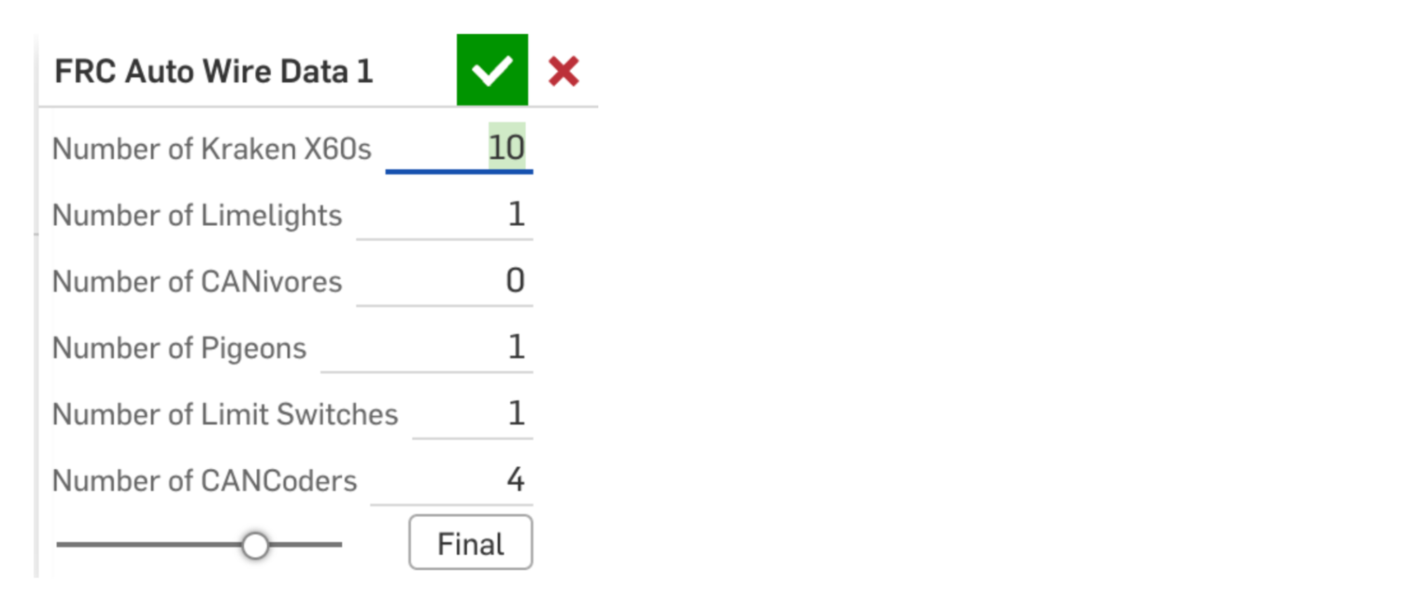
Outputs: a wire data table that lists every single required electrical component and wire
How it works: it creates an array of specifications to input into the existing Wire Data feature. It starts with a standard set of components my team uses (battery, radio, etc.), and then adds in the input number of non-standard components. I wrote a method to assign the proper power pins for each variety of component, which looks at the minimum and maximum voltage and the maximum wattage drawn. My feature then assigns wires for each component and uses the existing feature to create the actual wire data table that the user views and the next feature uses.

Feature 2: Auto Import Pin Components and Auto Wire Ref
Inputs: a mate connector location for each component (user input), and the wire data table from the previous feature (automatic)
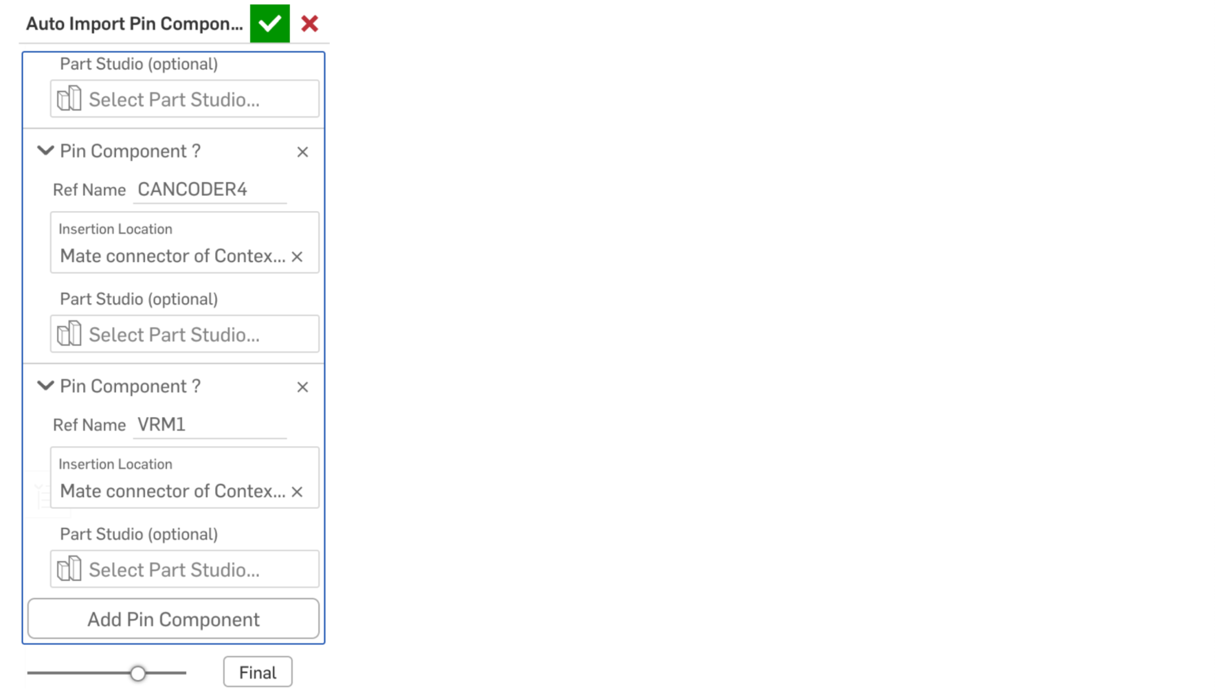
Outputs: imports the "pin components" (a skeleton of each component with pins designated by mate connectors) and automatically adds wire references to each pin. In essence, it tells the computer where each pin is/where each wire needs to go.
How it works: I struggled a lot with how best to structure this feature, and the frustratingly crude solution I came up with was to create a skeleton of each component with named mate connectors attached to each pin, and then writing code that would import them into the desired part studio, and call the existing wire ref feature using those mate connectors as inputs. Onshape did not have a way to attach names to mate connectors that would carry over into another part studio, so I had to write my own feature to create custom named mate connectors. The input uses an expanding interface based off of the existing wire route feature, allowing the user to add all of the components in one feature rather than having to use it separately for each part.
Feature 3: Reorganize Power Wires (Optional)
Inputs: none!
Outputs: reorganizes all of the power wires to optimize for the closest ports; edits the wire data table to reflect those changes
How it works: this optional feature uses a similar method to the one that assigns pins in Auto Wire Data, but it compares the locations of the ground pin mate connector (an arbitrary point I chose for consistency's sake) on each component and its power source to reassign the power pins. After the power wires are reorganized (or not, as the usage of this feature is entirely optional), the existing wire route feature can be used to add all of the actual wires into the CAD!